3D Representation
The 3D picture on the first monitor moves using the numbers the CPT sends: positions, speed, pressure and so on. It is a guide to what the machine is doing. It is not an exact copy of the machine. When you need an exact value, read the number on the screen.
How far can you rely on it?
| What the picture shows | |
|---|---|
| Follows the machine | The picture moves when the real part moves. Use it to see direction and roughly where the part is. Sprocket turning; Twister turning; Twister moving up and down. |
| Approximate | The picture is based on the real value but is rounded, scaled or drawn as a repeating pattern. Use it as a rough guide only. Number of rods in the folder; Rods moving through the guide; Rod string going down (CPT depth); Drive-unit wheels spinning; Drive-unit clamp opening. |
| Not connected | The picture does not show this at all. Read it on the screen. Oil level, temperature and pressure of the SHPU; Folder tension and speed; Alarms and errors; Twister end switches; Status of each drive unit. |
Folder and rods
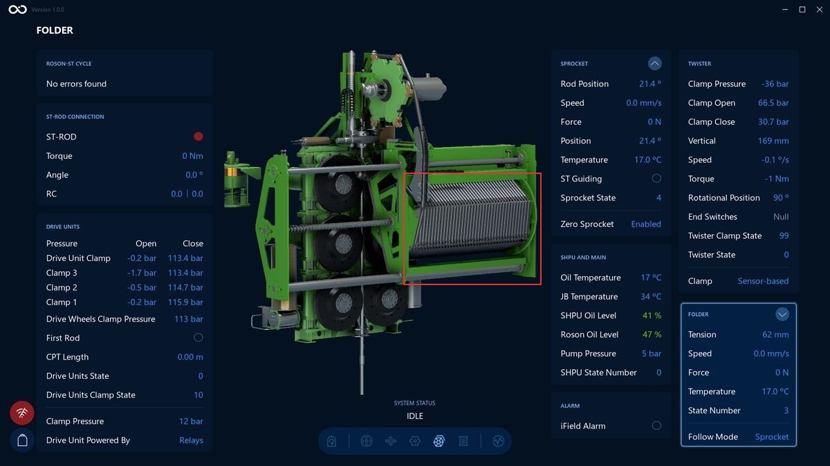
It follows: Rod Number.
- The folded rods in the picture get fewer in steps. One step for every 6 rods.
- The picture jumps from step to step. The real folder moves smoothly.
Keep in mind
- The picture assumes a fixed number of rods in total (132 on the CPT-100, 204 on the CPT-200). This number is built into the model, it is not sent by the machine.
- Use the Rod Number value on the screen for the exact count.
Rods
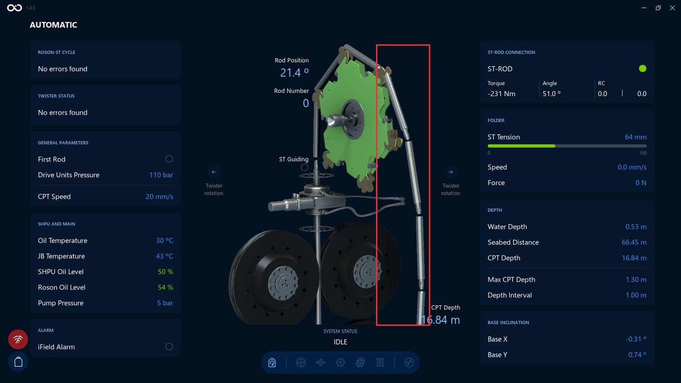
It follows: CPT Depth and Sprocket Position.
- The rods travel around the sprocket and down the right-hand side as the sprocket turns. This is a repeating animation. The same tubes are used again and again.
- The long straight rod below the twister lowers as the CPT depth increases. The picture shows full travel at 50 m on the CPT-100 and at 80 m on the CPT-200.
Keep in mind
- Do not count the rods in the picture. They are a repeating pattern, not the real rods.
- The depth in the picture is a rough guide. Use CPT Depth on the screen for the real value.
Drive units
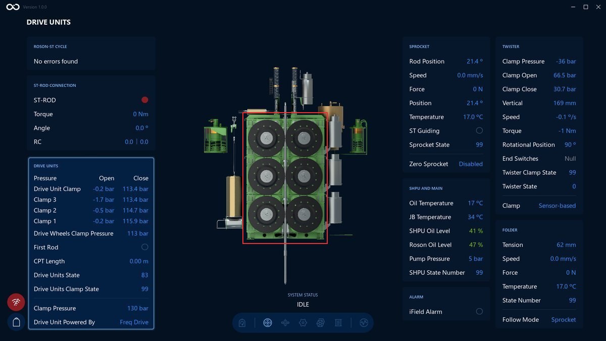
It follows: Speed, State and Clamp Pressure.
- The wheels spin when the drive unit has a speed. The direction follows the drive unit state.
- The wheels move together and apart with the clamp pressure.
Keep in mind
- How fast the wheels spin in the picture is for show. Do not use it to judge how fast the rods move.
- Which spin direction means push and which means pull is to be confirmed.
- At normal working pressure the wheels will look fully closed (to be confirmed).
Sprocket
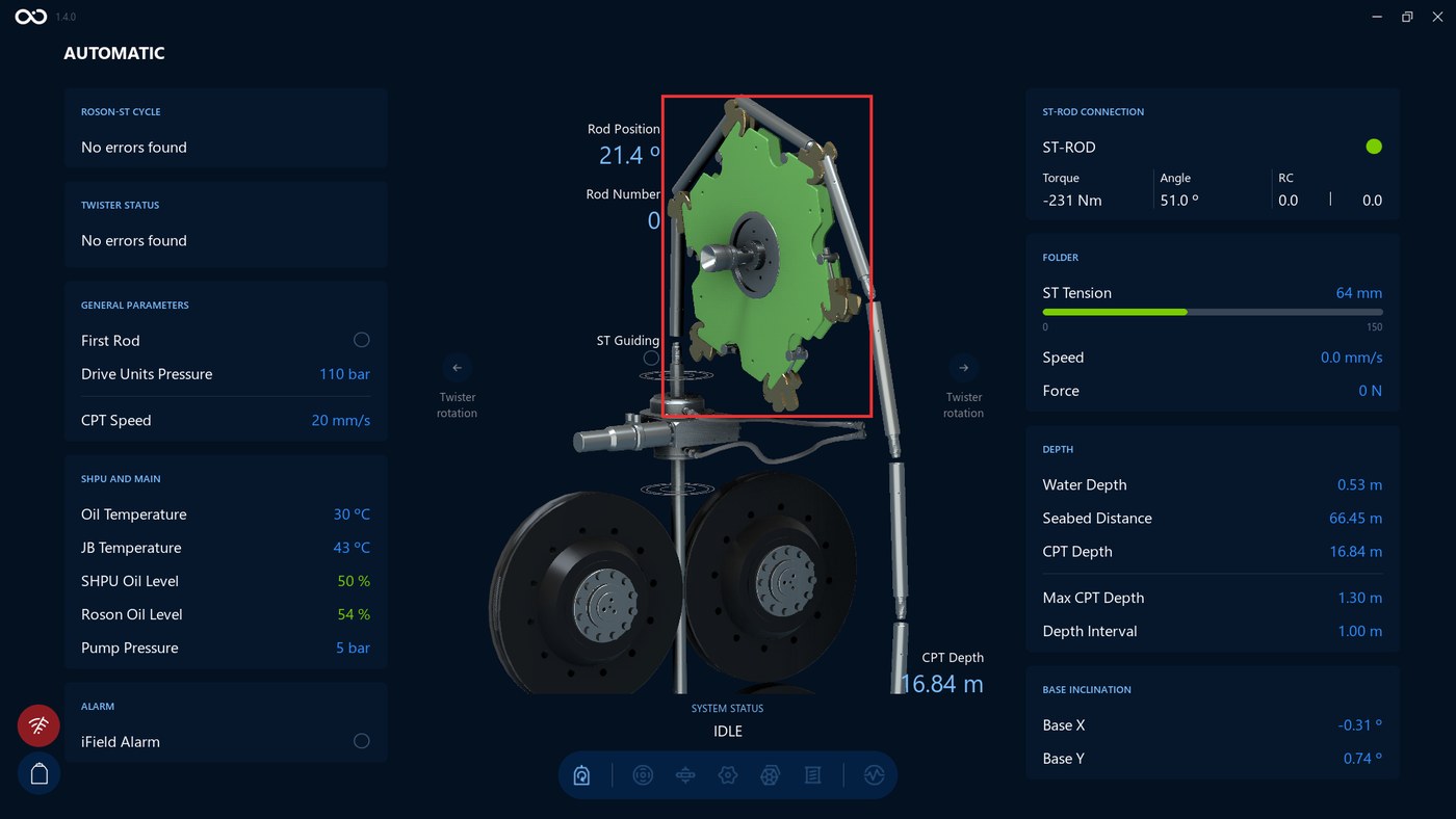
It follows: Sprocket Position.
- The sprocket and the parts around it turn when the real sprocket turns.
Keep in mind
- The picture repeats the same movement six times for every full turn. It shows how far through the current step the sprocket is.
- Use the Sprocket Position value on the screen for the exact angle.
Twister
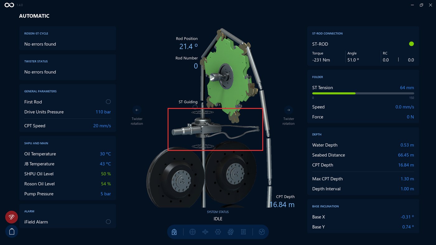
It follows: Twister Position and Twister Position (up and down).
- The twister turns left and right and moves a little up and down when the real twister does.
- The rubber wire at the twister bends and lifts with it. The clamp lights green for one range of clamp states.
Keep in mind
- The twister turns by 50 degrees at most in the picture, however far the real one turns.
- The up and down movement is small and scaled.
- The picture does not show the end switches. Use the Twister screen for those.
SHPU
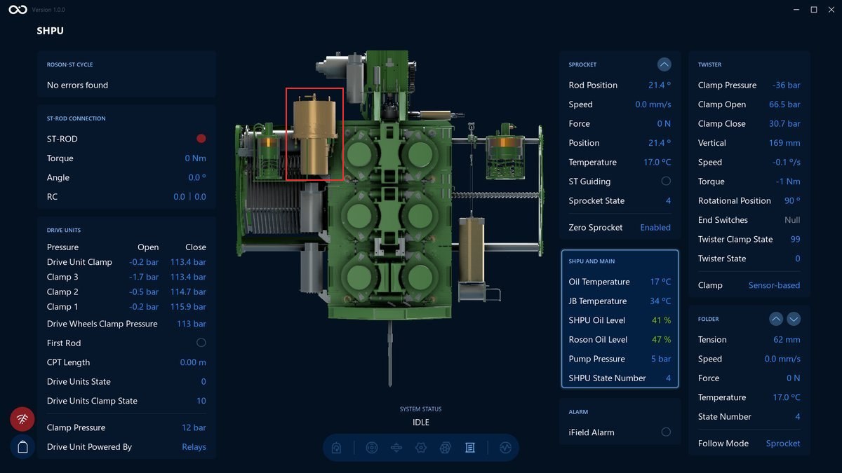
It follows: Nothing.
- The SHPU and the compensators are drawn as fixed parts. They only appear or disappear when you change screen.
Keep in mind
- The oil level, temperature and pressure are not connected to the picture. The oil in the picture does not go up or down.
- Read these values on the screen.
Using the picture safely
- Use the picture to see what is moving and in which direction.
- Use the numbers on the screen to find out how much.
- If the picture and the numbers disagree, trust the numbers.
Next section
In this section you've learned what the 3D picture shows, how it moves and how far you can rely on it. Feel free to start learning the controls by following this link: Control Interface.