Automatic Control Screen
In this section we will have a closer look at how you can use the Automatic screen to control the system during the CPT operation in Automatic mode.
What is the Automatic mode?
The automatic mode is used to operate every Roson function throughout a CPT on an abstraction level. You can treat this mode as driving a car on an automatic transmission. Unlike Manual Control mode, you can operate with automatic commands without the need to control every small part of the process.
Navigation
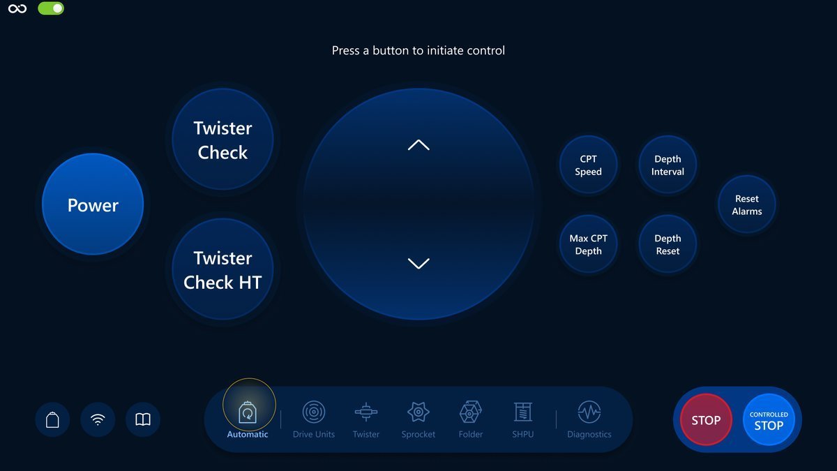
Tap on Automatic in the navigation bar for navigation. Here is an example:
Controls
We will have a look at a brief description of the controls, their responsibilities and also how it reflects the Visualization screen.
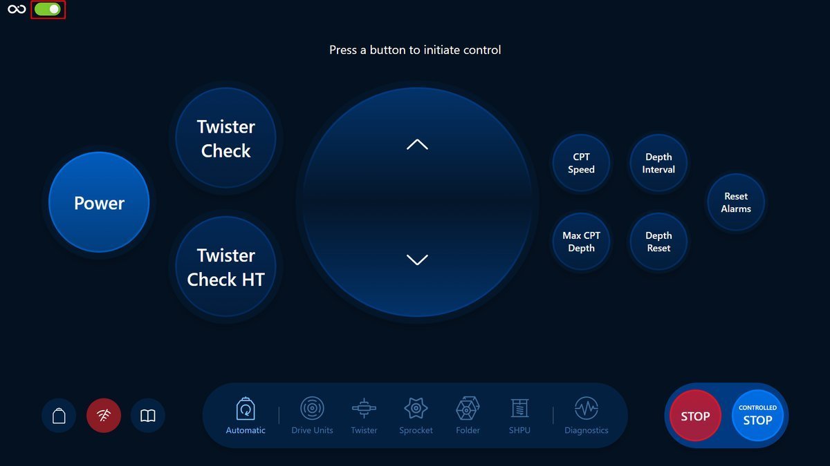
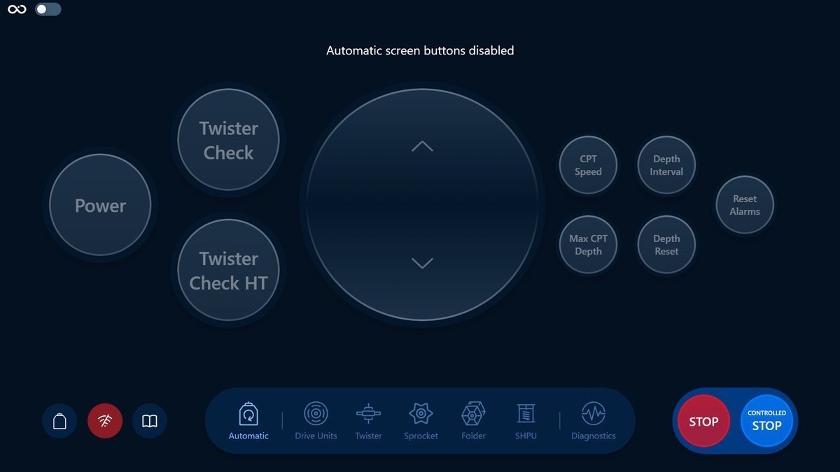
Button state toggle
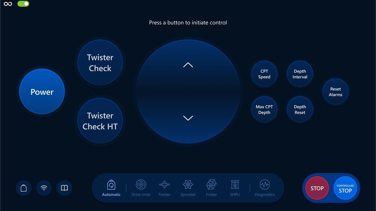
The state of the controls in the automatic screen can be changed with the toggle on the top left corner of the screen. Green means that the controls are enabled while grey means they are disabled.
Stop and Controlled Stop
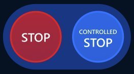
Stop: all movements will stop, the SHPU will restart automatically.
Controlled Stop: The drive unit will stop and the Folder + Sprocket pull the ST string on tension.
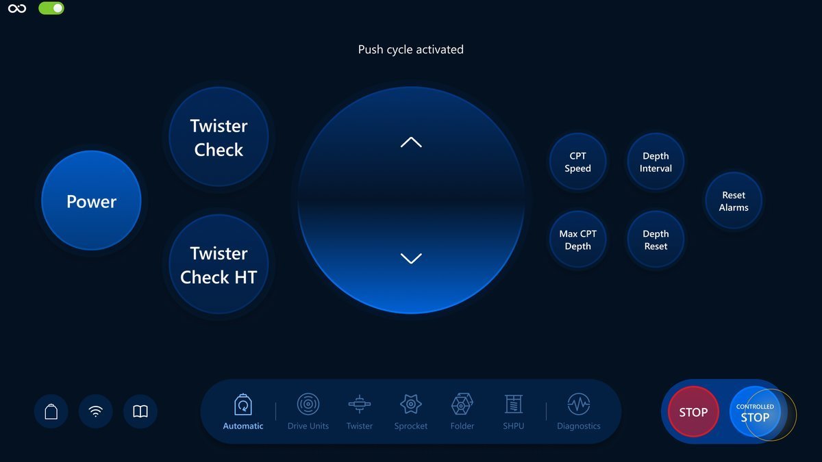
Here is an example of the Visualization screen after stopping the push cycle with the Controlled Stop button:
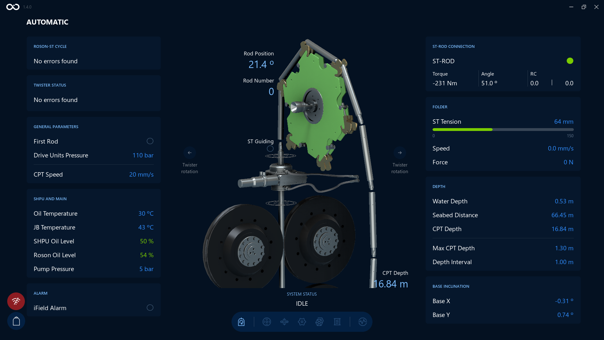
Power
Is responsible for powering on and off the ROSON-ST actuators, sensors and CPT. After Roson system is powered on you can power it off by tapping this button again.
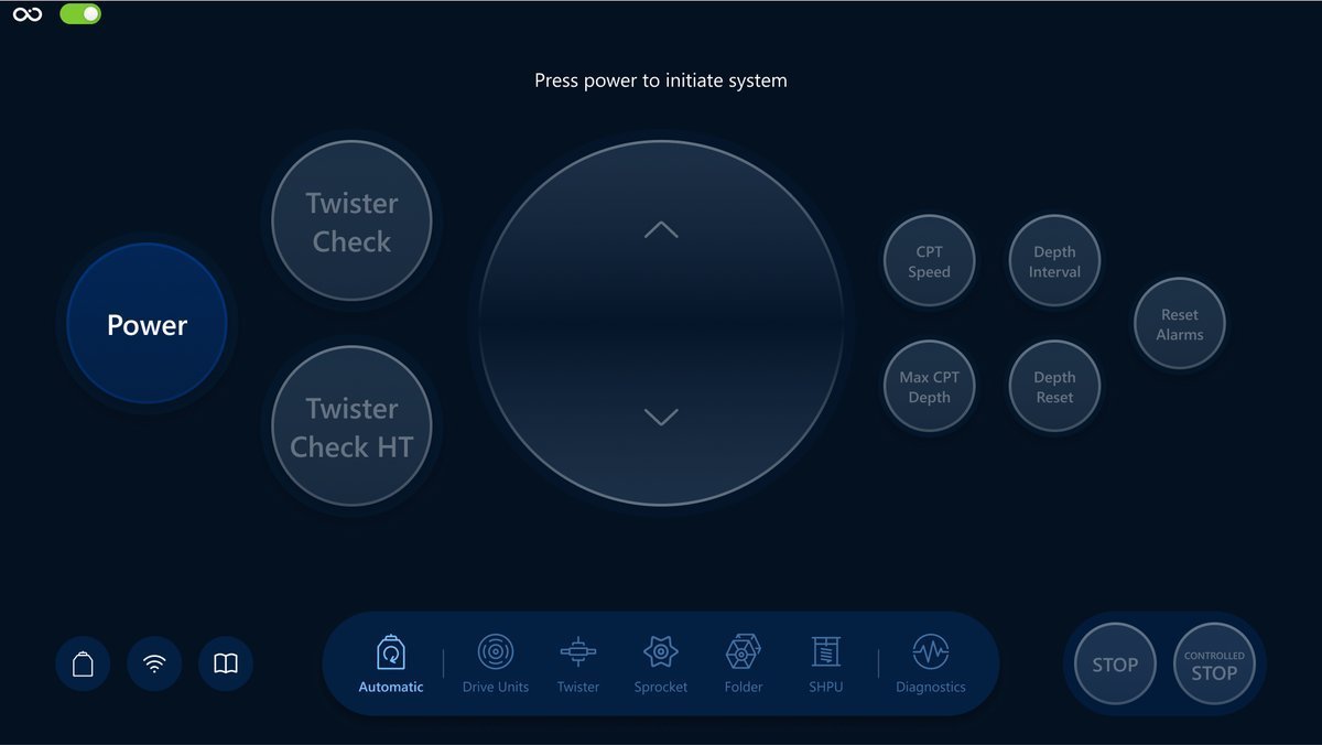
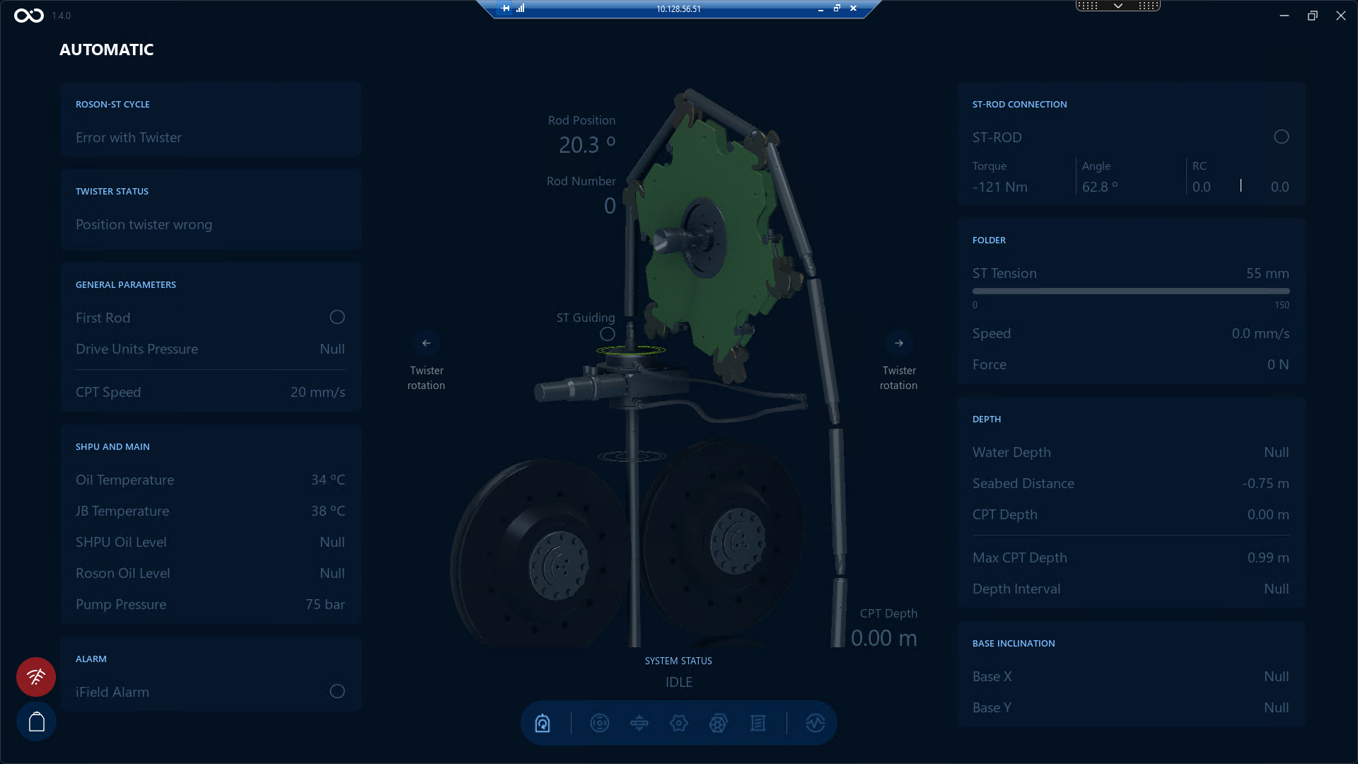
Here is an example of Controls and Visualization screen when the system is powered off:
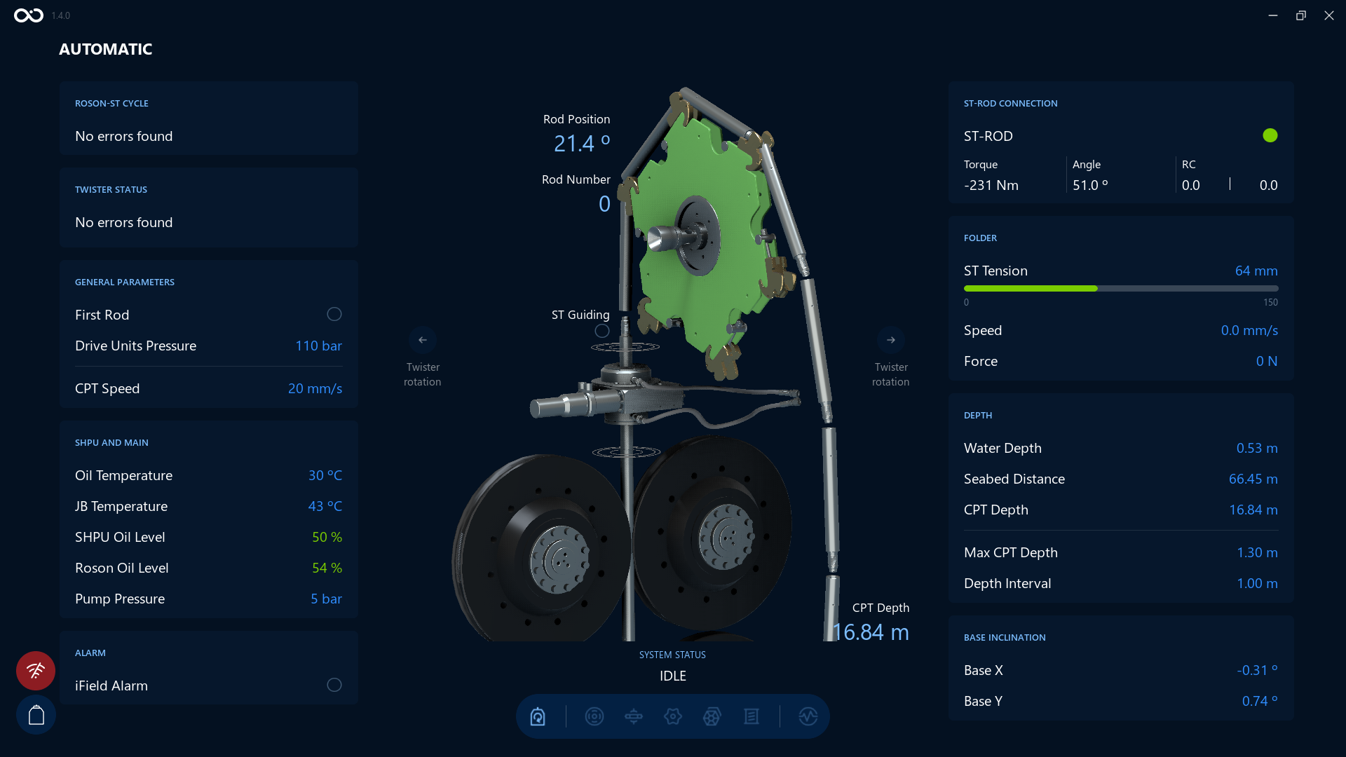
And this is an example when the system is powered on:
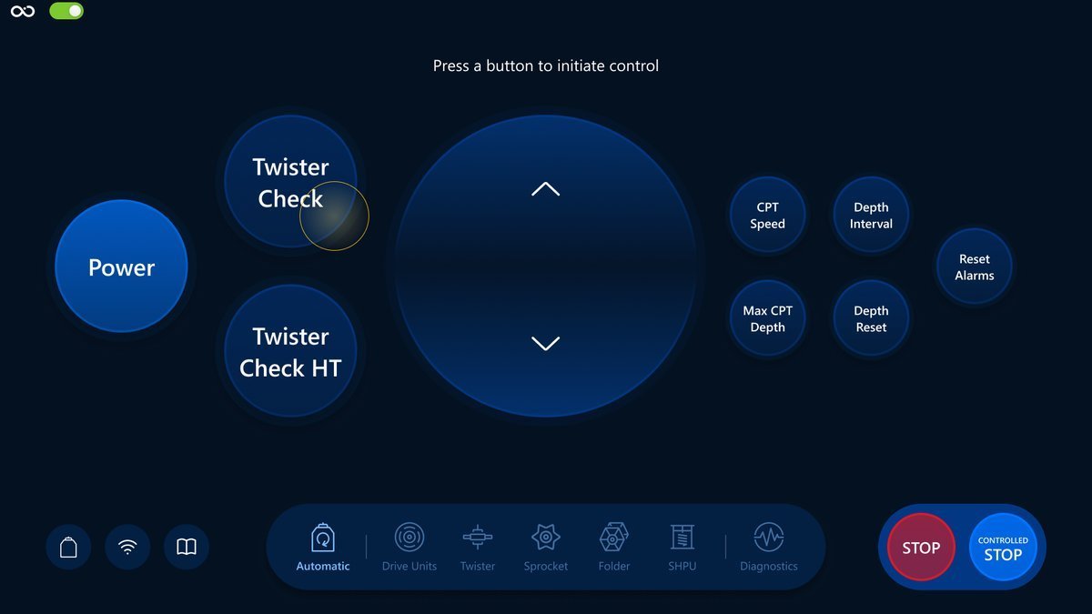
Twister Check
Checks rotation, clamping and end switches.
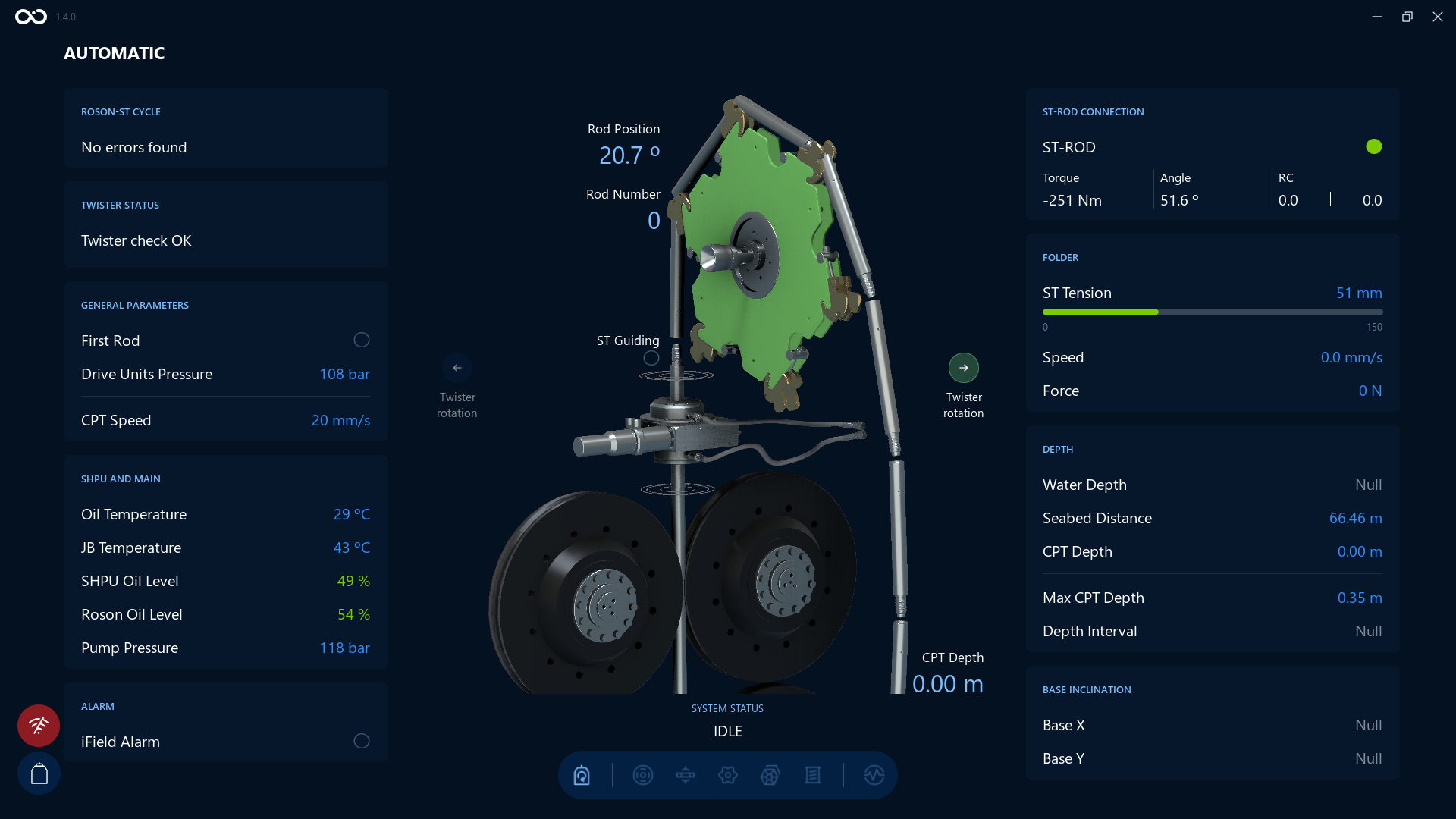
Example of the Visualization screen when the Twister Check command is finished with success. You can see the Twister Status on the top left side is changed to Twister Check OK.
Twister Check HT
The same behavior as Twister Check but with a higher torque.
Twister Rotation Arrows
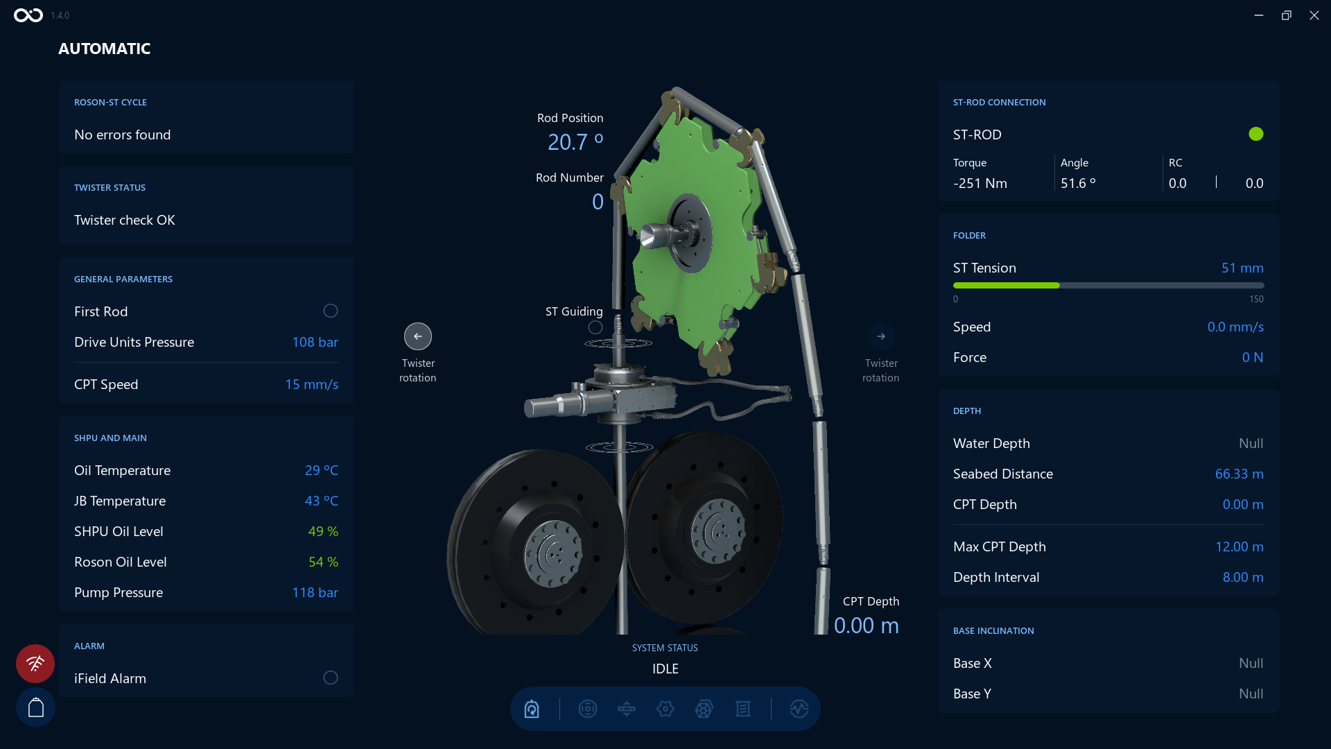
Next to the twister disc in the Visualization screen, you'll see two arrows labeled Twister rotation — one on the left, one on the right. These give the operator the same information as the equivalent indicator in APV's software, using a different color scheme:
| State | Meaning |
|---|---|
| Disabled (grey) | The twister is not rotating |
| White, right arrow | The twister is rotating CW |
| White, left arrow | The twister is rotating CCW |
| Green, right arrow | The CW End Switch has been reached — the twister has rotated as far as it can go in that direction |
| Green, left arrow | The CCW End Switch has been reached |
If the twister has reached an End Switch, the corresponding arrow always shows green, even if a rotate command is still being sent in that direction.
Here is an example of the Visualization screen with the right Twister rotation arrow shown in green, indicating the CW End Switch has been reached:
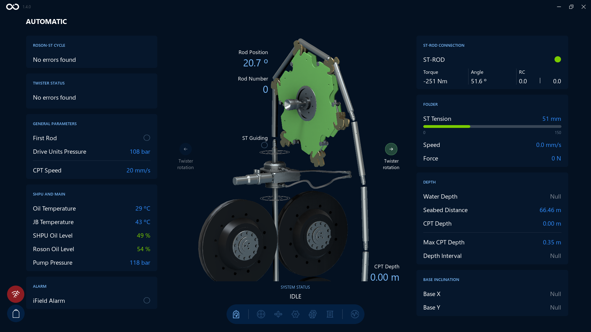
Here is an example with the left Twister rotation arrow shown in white, indicating the twister is actively rotating CCW:
Twister Vertical Movement Indicators
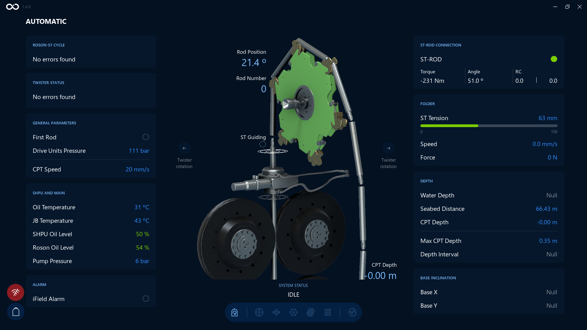
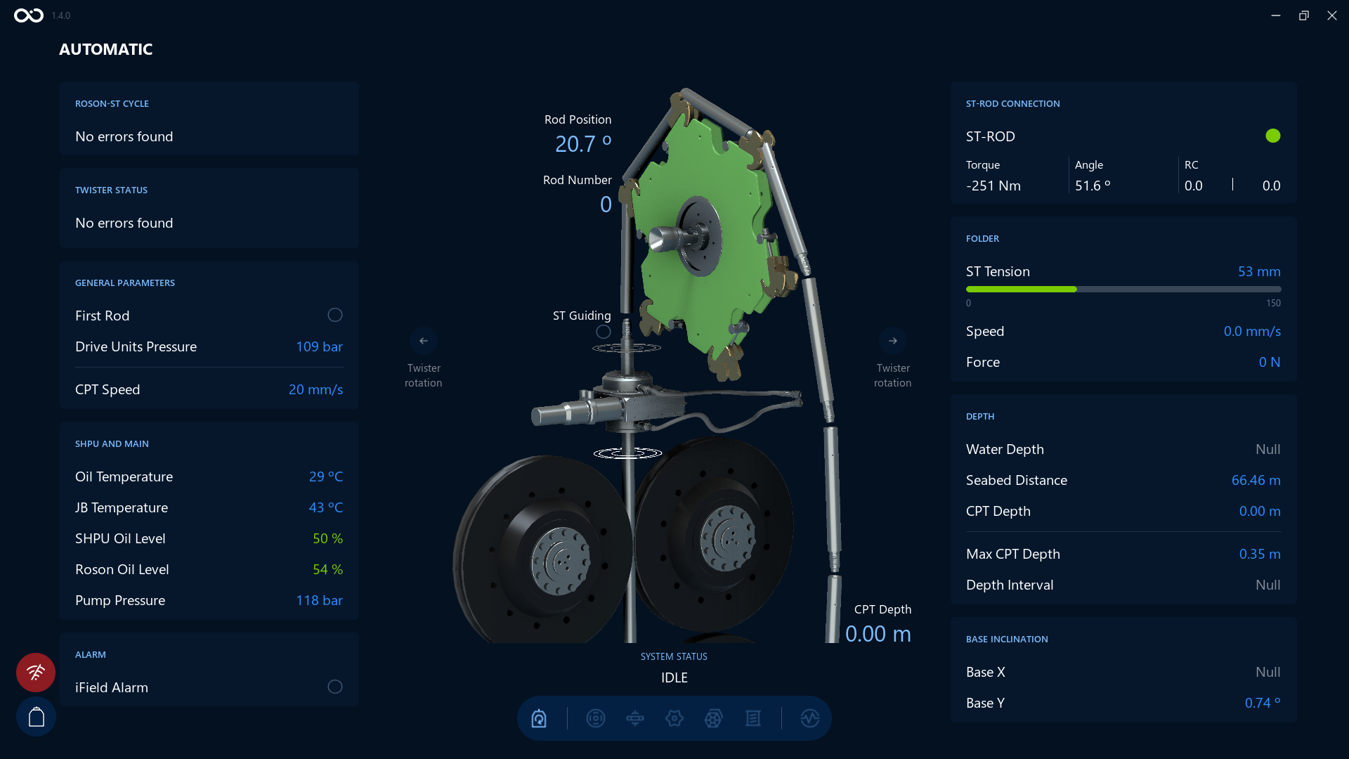
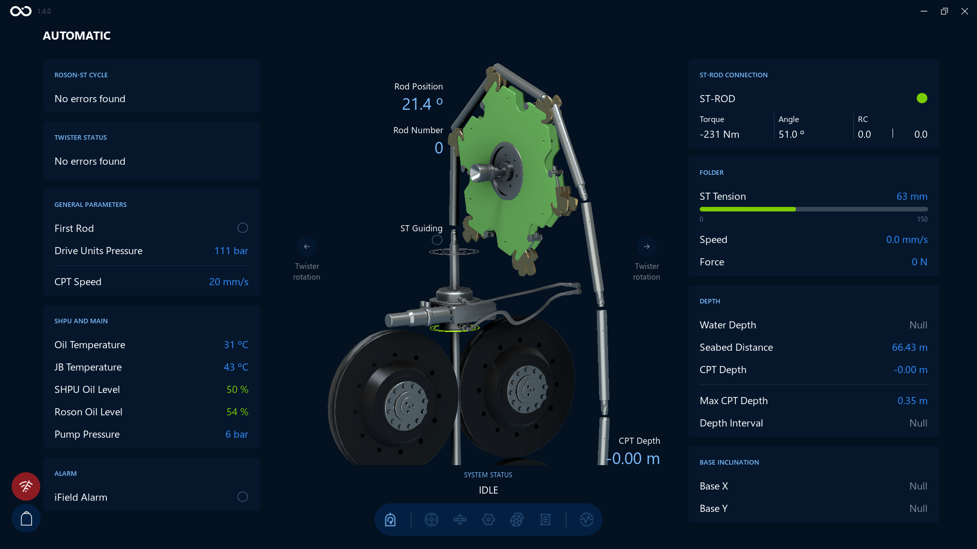
Above and below the twister clamp, two ring indicators show the twister's vertical travel, using the same color convention as the Twister rotation arrows: if the ring is white, it shows the direction the twister is currently moving; if it's green, the twister has reached its upper or lower travel limit.
Here are examples of the ring shown in white — while the twister moves up, and while it moves down:
And here is an example of the ring shown in green, once the twister has reached its lower travel limit:
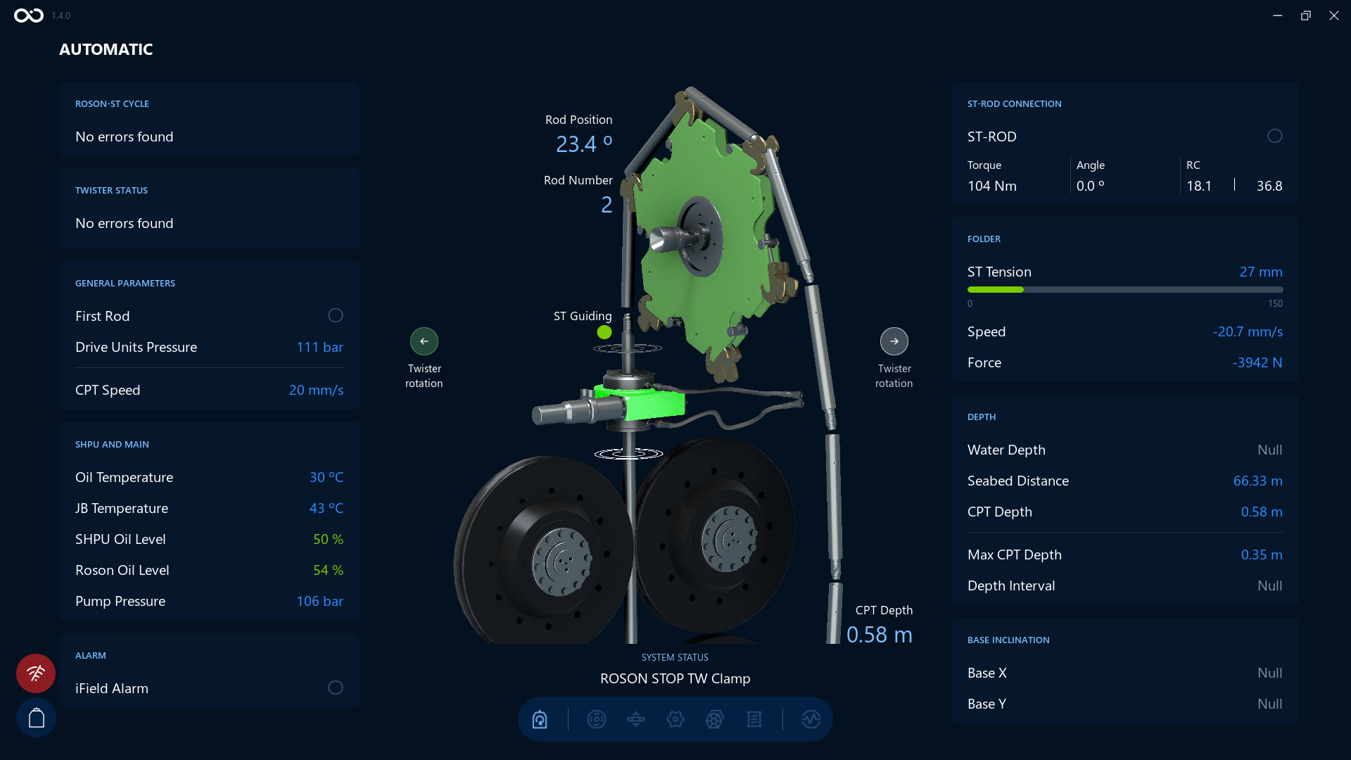
Twister Clamp Indicator
The rectangle at the center of the twister assembly is highlighted in green when the twister clamps are closed — the same color convention used by APV.
Here is an example with the clamp indicator highlighted in green, indicating the twister clamps are closed:
Pull and Push
Pull command starts the automatic ST pull cycle.
Push command starts the automatic ST push cycle.
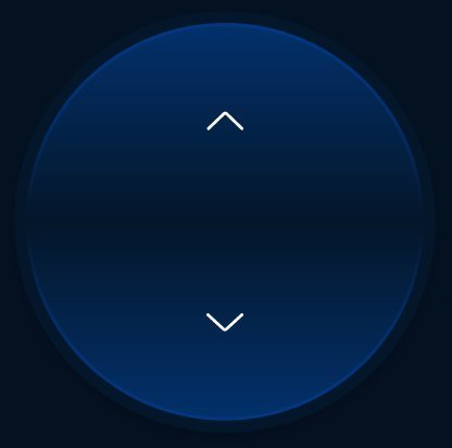
Let's have a look at a Push command. After an operator taps on a Push button, the Roson starts each function in order to push the cone downwards. For example, you can see the button color and the system status change on the Controls screen. And the status changes to Pushing on the Visualization screen:
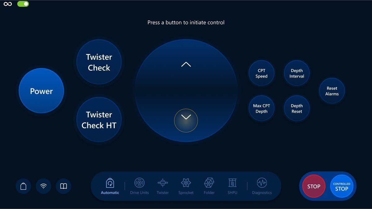
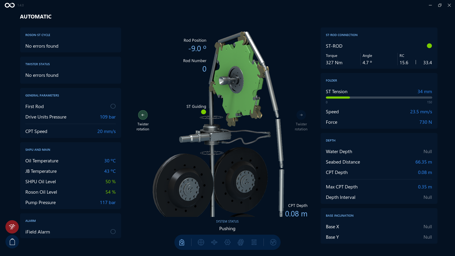
Operator can stop the process by tapping the Controlled Stop button on the bottom right side. The push cycle is terminated after the Controlled Stop command is executed. Here is an example of executing the Controlled Stop command and the status change on the Visualization screen:
CPT Speed
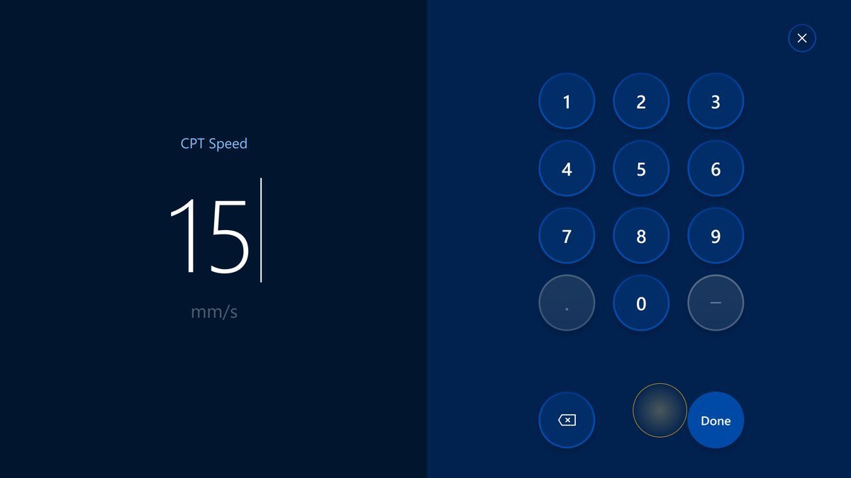
Opens a modal where an operator can set the CPT speed.
The button:
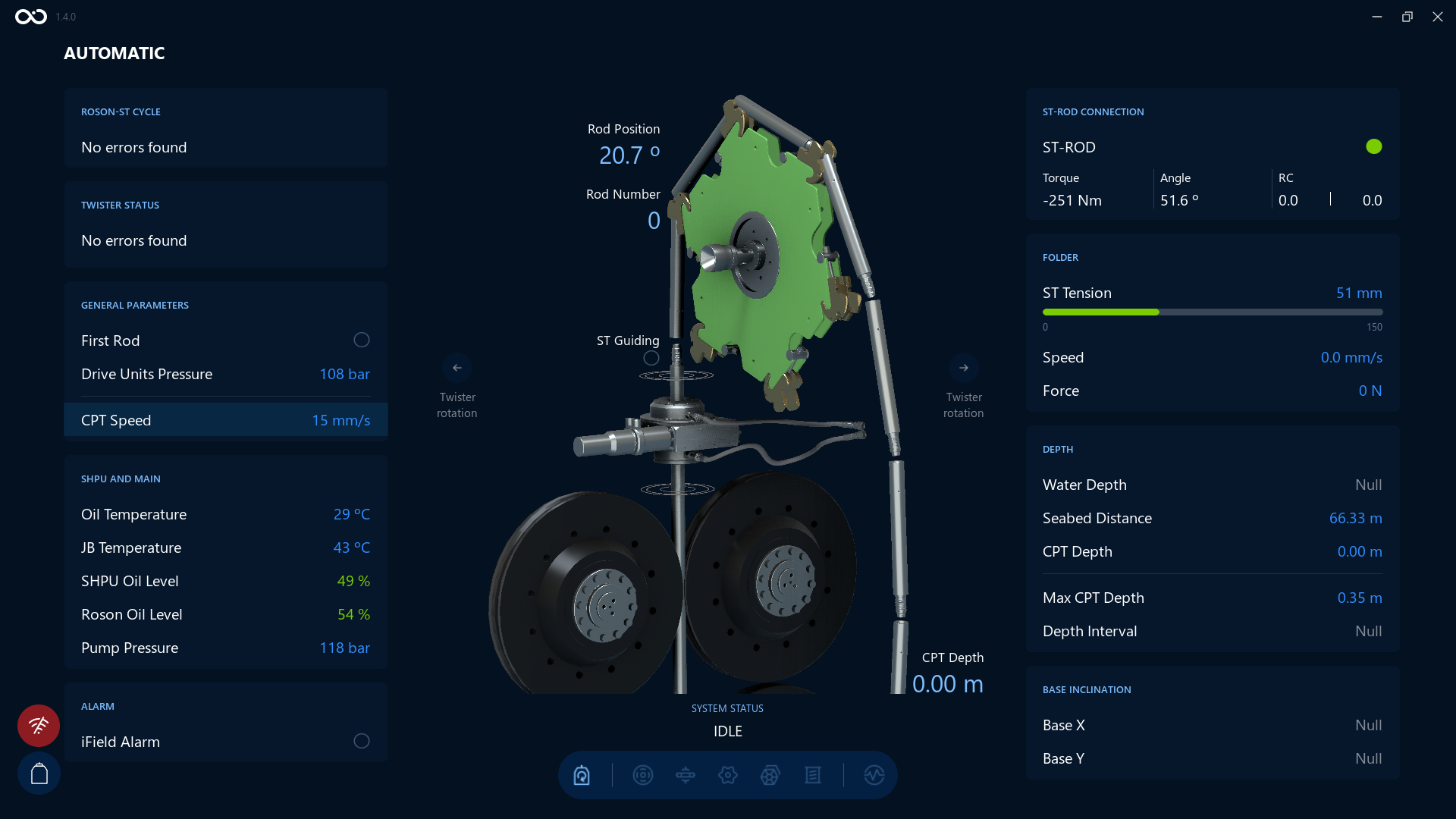
An example of the Visualization screen after changing the value for CPT Speed to 12 mm/s. We can see the CPT Speed value changed and highlighted on the bottom left side:
Depth Interval
With this command, it's possible to control the interval that the CPT will push.
This type of a command is a solution to execute push/pull of the CPT, where the Stop condition will go alongside the command. This will imply that as soon the command arrives to the Vessel and the CPT, the software will know at which depth it should send a controlled stop, mitigating the latency problem even in the worst conditions. The penetration will stop in pre-determined intervals set by the depth interval without the operator needing to stop the CPT.
For example, if the CPT requires to stop at every meter for additional subtests, then set the depth interval at 1.0m and it's only required to push without any additional input from the operator.
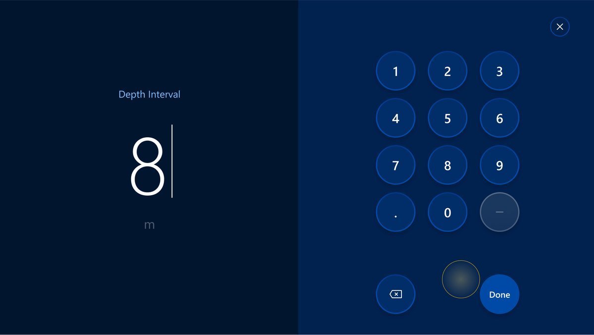
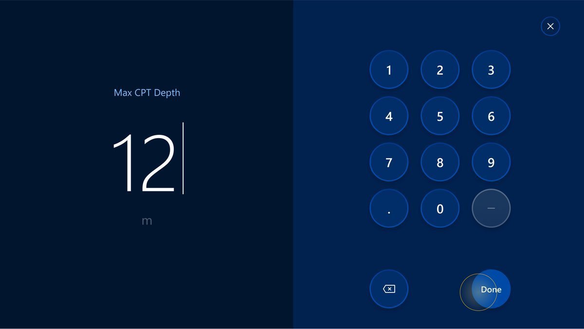
The button opens a modal where an operator can set the Depth Interval for CPT:
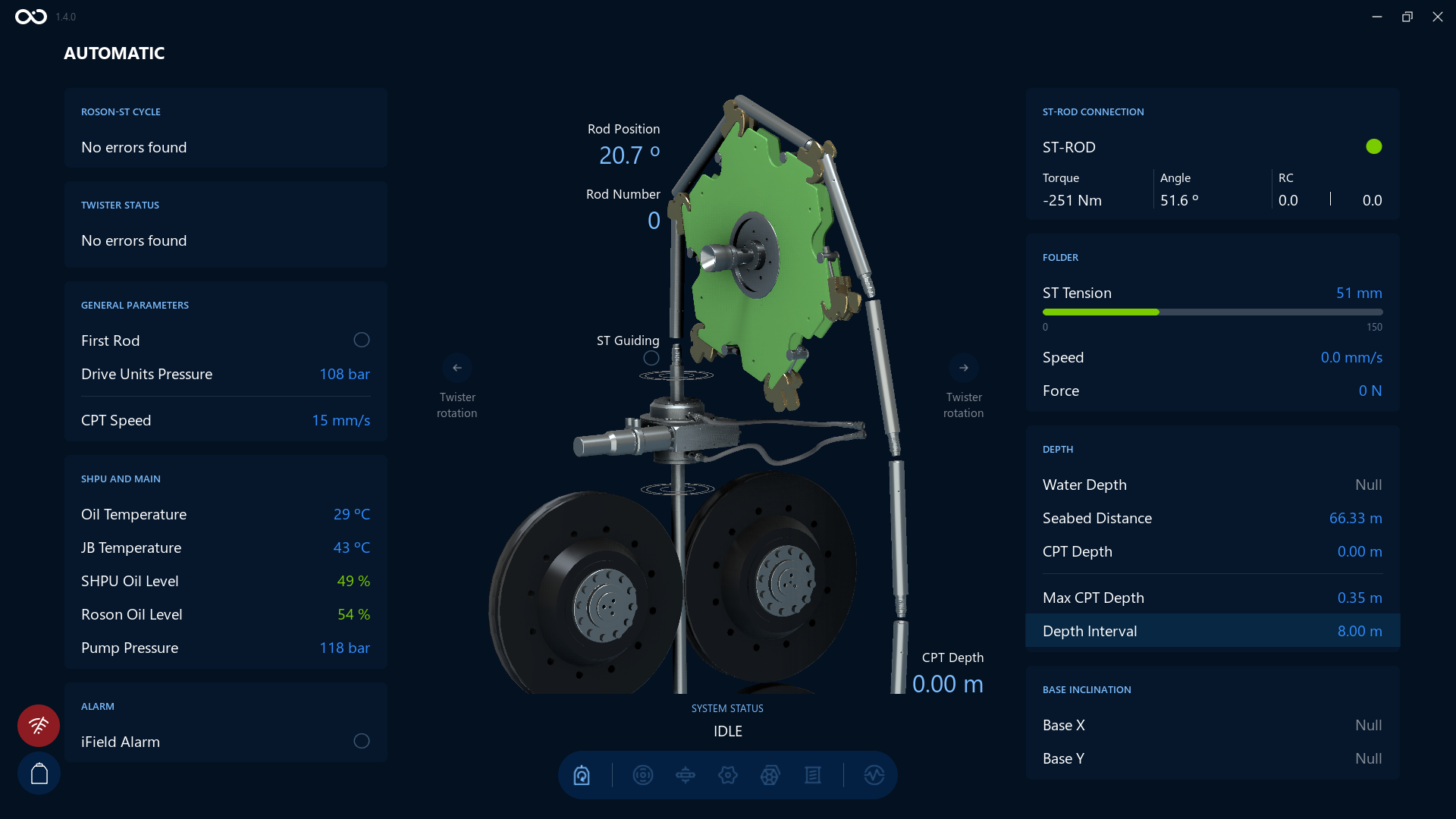
An example of the Visualization screen after changing the value for Depth Interval to 8m. We can see the Depth Interval value changed and highlighted on the bottom right side:
Reset Alarms
This function overrides the Ifield alarm and can be used when the alarm level is reached. The acoustic signal is switched off and the automatic cut-off of the hydraulic push system is cancelled.
The button:
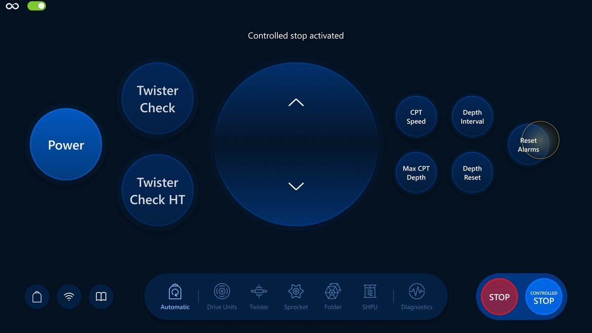
An example of the Visualization screen on about to click on Reset Alarms button:
Max CPT Depth
Opens a modal where an operator can set the maximum CPT Depth.
The button:
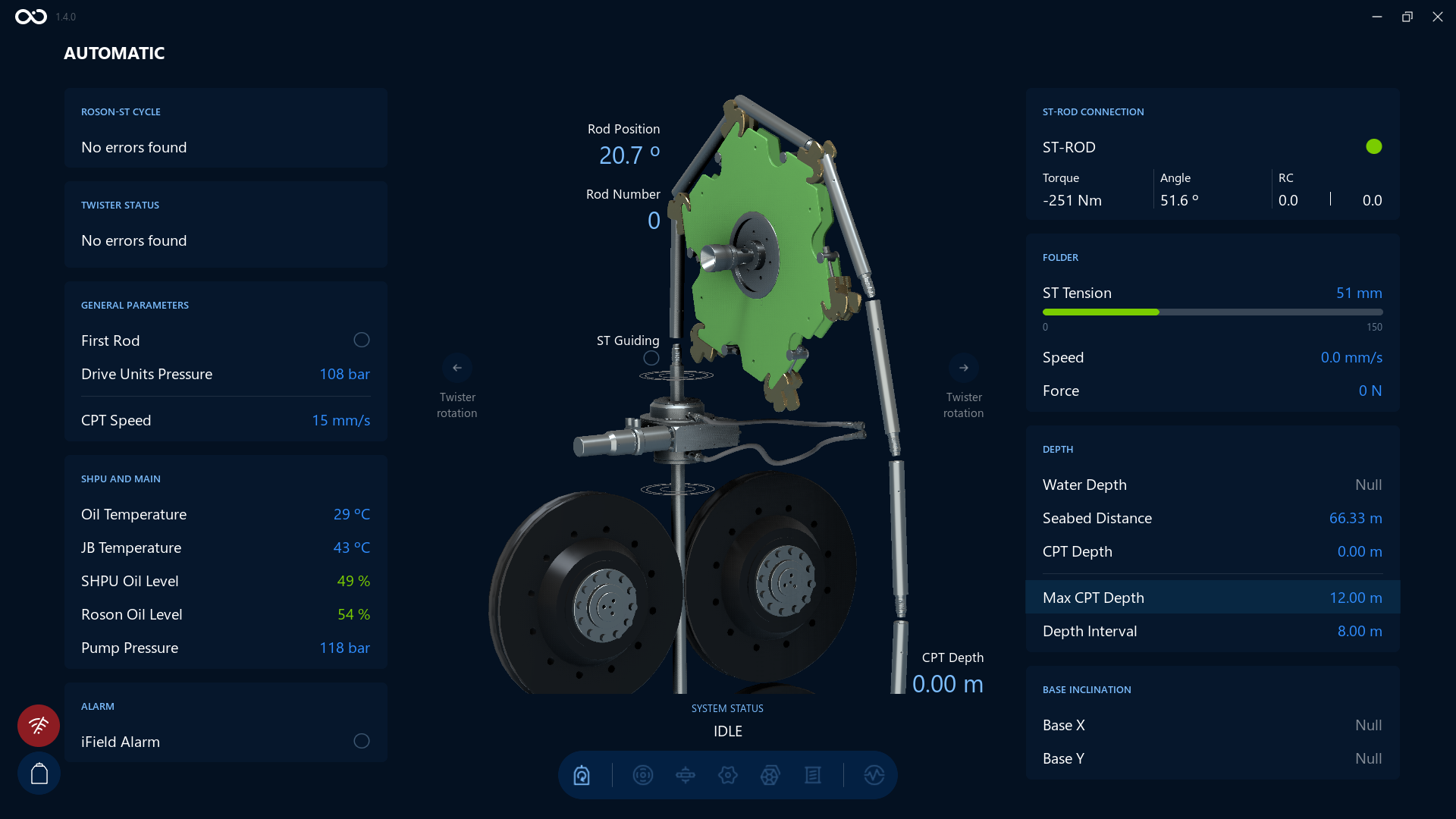
An example of the Visualization screen after changing the value for Max CPT Depth to 12m. We can see the Max CPT Depth value changed and highlighted on the bottom right side:
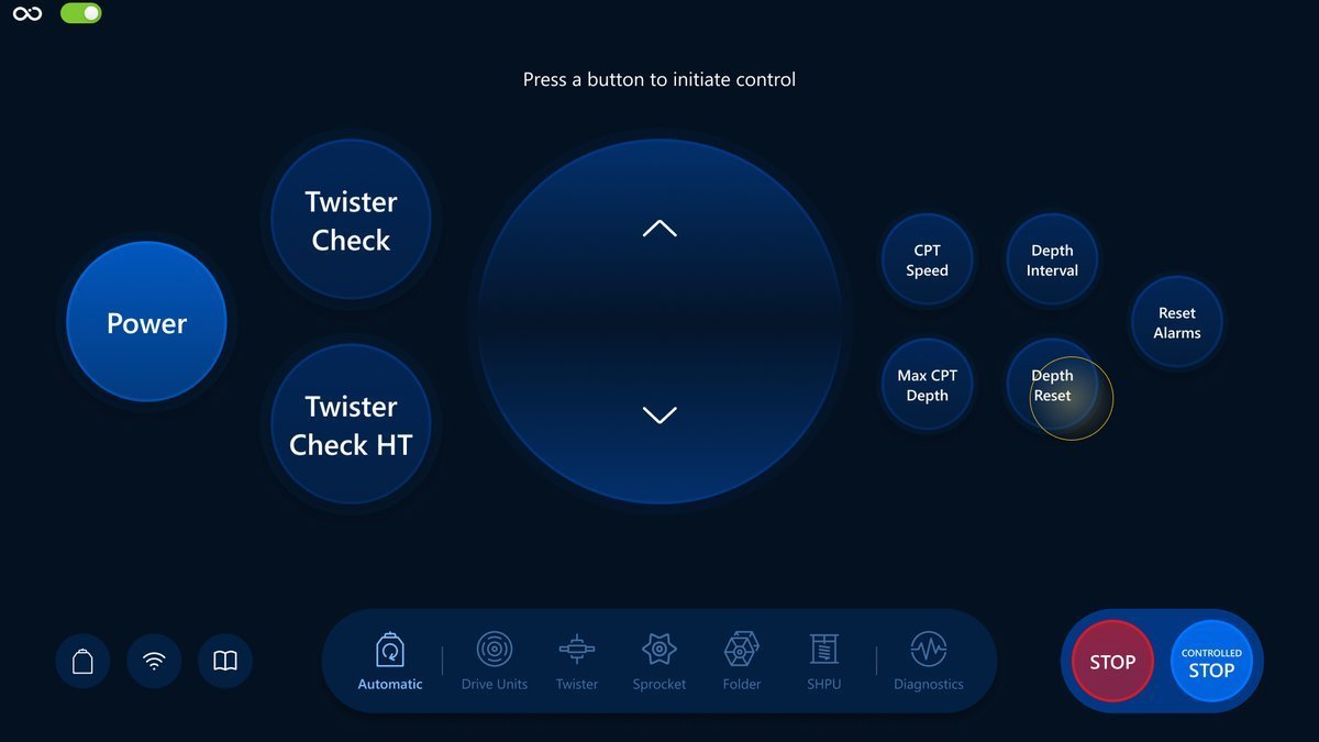
Depth Reset
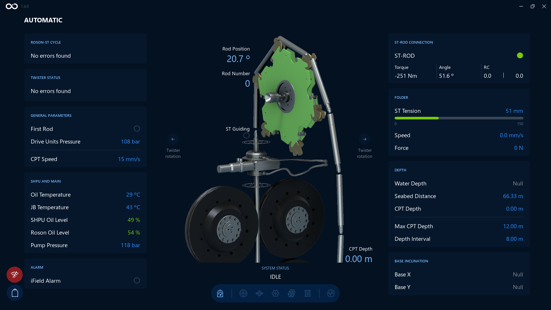
Resets the CPT Depth.
An example of the Visualization screen after tapping the Depth Reset button. We can see the CPT Depth value was reset on the bottom right side:
What's next?
Feel free to go to the next section and learn the Manual Mode in more detail: Manual Mode overview